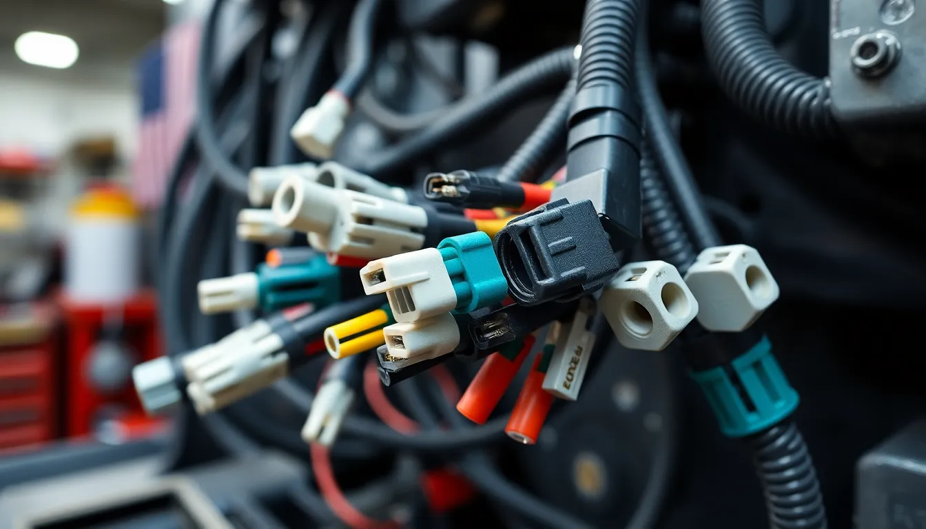
J1939 is the protocol backbone of heavy vehicles
Since the early 2000s, J1939 has been the dominant communication standard for ECUs in commercial vehicles — trucks, buses, agricultural machinery, construction equipment. Every major OEM from Volvo to Caterpillar to Cummins transmits engine load, vehicle speed, fuel consumption, axle weight, DPF status, and hundreds of other parameters over J1939.
The protocol sits on top of the CAN physical layer and uses 29-bit extended identifiers. Each message is identified by a Parameter Group Number (PGN) — an 18-bit value embedded in the CAN identifier — and carries Suspect Parameter Numbers (SPNs) inside the 8-byte payload. The 250 kbps baud rate that J1939 standardized decades ago was more than sufficient for the number of ECUs and the volume of data that trucks carried in 2005.
It is no longer sufficient in 2026.
Why J1939 needed to evolve: the bandwidth problem
Modern commercial vehicles carry 80 to 150 ECUs. ADAS systems generate radar point clouds. OTA update packages for engine calibrations can exceed 50 MB. Camera-based lane departure systems require continuous data streams. Body control modules, telematics units, instrument clusters, and aftertreatment systems all share the same bus.
Classic CAN at 250 kbps has a theoretical maximum throughput of roughly 25 kbps of useful payload data. At 500 kbps — the upper limit for classic J1939 — you reach perhaps 50 kbps. For a modern truck with active ADAS, this is a hard ceiling that the industry has been engineering around for years with gateway ECUs, secondary bus segments, and protocol bridges.
J1939-22, released in 2020–2021, solves this structurally. It brings CAN FD — the Flexible Data Rate extension of the CAN standard — into the J1939 framework.
J1939-22: what CAN FD actually changes
CAN FD modifies the CAN frame in two ways that matter enormously for heavy vehicle applications.
First, the payload grows from 8 bytes to up to 64 bytes per frame. J1939's transport protocol (J1939-21) was designed specifically to work around the 8-byte limit — splitting large messages across multiple frames with sequence counters, BAM announcements, and RTS/CTS handshakes. J1939-22 eliminates the need for transport protocol fragmentation in the vast majority of cases. A diagnostic response that previously required 12 fragmented frames now fits in a single CAN FD frame.
Second, and more consequentially for hardware engineers: the data phase runs at a different, higher bit rate than the arbitration phase. The arbitration phase — where ECUs compete for bus access using the same 29-bit identifier mechanism — remains at 500 kbps for J1939-22, preserving backward compatibility with classic J1939 devices on the same network. But once a node wins arbitration, it switches to a higher data rate — typically 2 Mbps in commercial vehicle implementations, with some automotive-derived applications reaching 5 or 8 Mbps — to transmit the payload.
This two-phase rate switching is where the physics of the bus become unforgiving.
What CAN FD does to the bus: the signal integrity challenge
At 250 kbps, a CAN bit occupies 4 microseconds. A signal distortion of 400 nanoseconds — easily introduced by a poorly chosen termination resistor, a long stub, or a moderate EMI source — represents 10% of the bit period and is typically absorbed by the CAN controller's bit sampling mechanism without error.
At 2 Mbps, a bit occupies 500 nanoseconds. That same 400 ns distortion now represents 80% of the bit period. The bus either missamples the bit or triggers a bit error, causing the frame to be retransmitted. At 5 Mbps, a bit is 200 nanoseconds. There is no margin left.
This compression of the bit period means that every passive component on a CAN FD bus — every centimeter of cable, every connector, every stub, every protection component — must be evaluated at CAN FD frequencies, not at the 250 kbps frequencies that drove component selection for a decade.
For devices attached to J1939-22 networks in heavy vehicles, three component choices determine whether the device communicates reliably or fails silently under operating conditions: the common mode choke, the TVS diode, and the transceiver IC.
The common mode choke: filtering noise without destroying the signal
A common mode choke (CMC) is placed in series with the CAN H and CAN L lines at the point where the bus enters a device. Its purpose is to suppress common mode noise — interference that appears identically on both lines simultaneously — while passing the differential CAN signal (which appears in opposite polarity on CAN H and CAN L) with minimal attenuation.
In a heavy vehicle, common mode noise sources are severe. A diesel engine's alternator generates broadband noise from 100 kHz to 10 MHz as rotor field coils commutate. Starter motor engagement produces current transients that couple inductively into every cable harness within a meter. 24V switching regulators for cab electronics radiate at their switching frequency and harmonics. Injector drive circuits in modern common-rail diesels switch currents of 20+ amperes in microseconds, generating conducted and radiated EMI across the entire CAN FD frequency range.
The critical parameter for a CAN FD common mode choke is common mode impedance across the 1 MHz to 8 MHz range — the frequency range that corresponds to CAN FD data phase bit rates of 2 to 8 Mbps, plus their harmonics. A CMC specified and verified only to 500 kHz — adequate for classic CAN — may have its self-resonant frequency within the CAN FD operating range. Above self-resonance, a CMC becomes capacitive and provides no common mode attenuation. It may actually amplify noise at that frequency.
Equally important is differential mode impedance. An ideal common mode choke presents zero differential impedance — the two windings cancel each other perfectly. In practice, winding asymmetry and distributed capacitance introduce differential mode impedance that, at CAN FD frequencies, can distort the signal waveform, shift bit timing, and trigger receiver errors.
For XENTRON ULTRA, CMC selection involved characterization of insertion loss curves across 100 kHz to 10 MHz under operating current, at -40°C and +125°C, and under common mode voltages representative of actual vehicle harness conditions. A CMC that measures well on a bench at room temperature may perform completely differently at the end of a 10-meter harness in a 40-ton truck doing 90 km/h on a motorway.
TVS diode selection: protecting against what the vehicle actually generates
The transient voltage environment of a heavy commercial vehicle is categorically different from a passenger car — and worse than most bench engineers expect.
A 24V truck electrical system is the standard for European and heavy-duty commercial vehicles. Under normal conditions, the bus voltage sits at 24–28V. But load dump — the transient generated when a large inductive load (typically the alternator field winding or a major solenoid) is suddenly disconnected — can produce voltage spikes of 120V or higher on a 24V system, with rise times under 1 microsecond and durations of tens of milliseconds. ISO 7637-2 defines the pulse profiles for automotive transients; pulse 5a (load dump) is particularly relevant for 24V commercial vehicle systems.
The CAN transceiver ICs used for J1939-22 have maximum bus pin ratings typically in the range of -27V to +58V. A 120V load dump transient that reaches the bus pins without clamping destroys the device. A single destroyed transceiver in a gateway ECU can isolate an entire bus segment.
TVS diode selection for CAN FD adds complexity that does not exist for classic CAN. The fundamental protection requirement is the same: clamp voltage must be below the transceiver's absolute maximum rating, response time must be faster than the transient rise time, and power dissipation must be sustainable for the pulse duration.
But CAN FD adds a critical constraint: junction capacitance. A TVS diode is a reverse-biased junction, and all reverse-biased junctions have capacitance. At 250 kbps, 50 pF of TVS capacitance per CAN line is typically acceptable — the RC time constant at the bus impedance is small relative to the bit period. At 5 Mbps, 50 pF of capacitance per line interacts with the 60-ohm bus impedance to produce an RC corner frequency around 53 MHz. The first harmonic of a 5 Mbps CAN FD signal is at 5 MHz — well inside the filter's passband. But the signal's rise time, which determines eye opening, involves frequency content up to 10–50 MHz. Excess TVS capacitance rounds the signal edges, closes the eye diagram, and introduces the kind of bit timing errors that appear intermittently in the field and resist root cause analysis in the lab.
For XENTRON ULTRA, TVS selection was constrained to devices with junction capacitance below 15 pF per CAN line, bidirectional clamping, and a clamping voltage verified below the transceiver's absolute maximum at the ISO 7637-2 pulse 5a current profile for 24V systems. This combination provides protection against the actual transient environment of a heavy vehicle without degrading CAN FD signal integrity.
Transceiver IC selection: not all CAN chips are CAN FD
This is the most frequently misunderstood component decision in CAN FD hardware design.
Classic CAN transceivers — the TJA1050, MCP2551, PCA82C251, and their many variants — are not capable of CAN FD operation. Their internal circuit topology, input hysteresis, and loop delay specifications were designed for 1 Mbps maximum. At 2 Mbps CAN FD data rates, these devices introduce asymmetric delays between the transmit data input and the CAN bus output, and between the CAN bus input and the receive data output, that cause bit timing violations. The CAN FD bit timing calculations assume a symmetric loop delay; asymmetry shifts the sample point in a way that accumulates across long frames and causes receiver errors.
J1939-22 implementations require transceivers explicitly qualified for CAN FD operation and compliant with ISO 11898-2:2016 — the revision of the CAN physical layer standard that introduced requirements for CAN FD.
Key specifications to evaluate in transceiver selection for a J1939-22 device in a commercial vehicle environment:
Loop delay symmetry: the difference between transmitter loop delay (TXD to CANH/L) and receiver loop delay (CANH/L to RXD) must be specified and minimized. For 5 Mbps CAN FD, 10 ns of asymmetry represents 5% of the bit period — significant when total bit timing budget is already constrained by bus length and propagation delay.
Common mode range: heavy vehicle harnesses can impose common mode voltages of ±25V under fault conditions. The transceiver's common mode operating range must cover this range without entering a state that disrupts bus communication or triggers spurious frames.
ESD and short-circuit protection: commercial vehicle connectors are mated and unmated under power during service. The transceiver must survive electrostatic discharge at the bus pins (IEC 61000-4-2 up to ±8 kV contact discharge is a common requirement) and sustained short circuits to battery voltage and ground.
Automotive qualification: AEC-Q100 Grade 1 qualification covers -40°C to +125°C operating range, which is the relevant range for a device mounted in a commercial vehicle cab or underhood.
For XENTRON ULTRA, the transceiver selection process evaluated ICs from Texas Instruments (TCAN series), NXP (TJA104x series), and onsemi (NCV7xxx series) against these criteria under the specific operating conditions of the target deployment: 24V vehicle systems, underhood-adjacent mounting temperatures, multi-year operational lifetime requirements, and the J1939-22 bit timing requirements at 2 Mbps data phase with 500 kbps arbitration phase.
XENTRON ULTRA's CAN FD signal improvement capability
The component engineering decisions described above are not academic. They define whether a telematics or diagnostic device connected to a J1939-22 bus on a commercial vehicle actually reads data reliably after 50,000 kilometers of operation in Central Asian summer heat, Nordic winter cold, and the EMI environment of a 480 hp diesel engine.
XENTRON ULTRA's CAN FD interface incorporates the full signal conditioning chain: CMC selection verified at CAN FD frequencies under operating conditions, TVS protection characterized against 24V system load dump transients with capacitance constrained for 2 Mbps signal integrity, and a transceiver IC selected for ISO 11898-2:2016 compliance, loop delay symmetry, and AEC-Q100 Grade 1 automotive qualification.
The result is a device capable of reliable J1939-22 communication on commercial vehicle networks — reading all DTCs, FreezeFrame data, SPN values, and extended 64-byte payload messages that J1939-22 enables — without the signal errors, missed frames, and intermittent connectivity that characterize devices designed to classic CAN specifications and retro-fitted to CAN FD networks.
J1939-22 represents a genuine step forward for commercial vehicle diagnostics and telematics. More data per frame, no transport protocol fragmentation overhead, and headroom for the data volumes that modern ADAS and OTA-capable trucks generate. But realizing that capability in hardware that operates reliably in the actual truck environment requires solving the signal integrity problem first — at the component level, before the software is ever written.
That is the engineering foundation of XENTRON ULTRA.